Hardware Overview
This page covers the physical design of the NanoVNA-F V3 — what each port does, how the buttons work, and what the LEDs are telling you.
Front panel
Section titled “Front panel”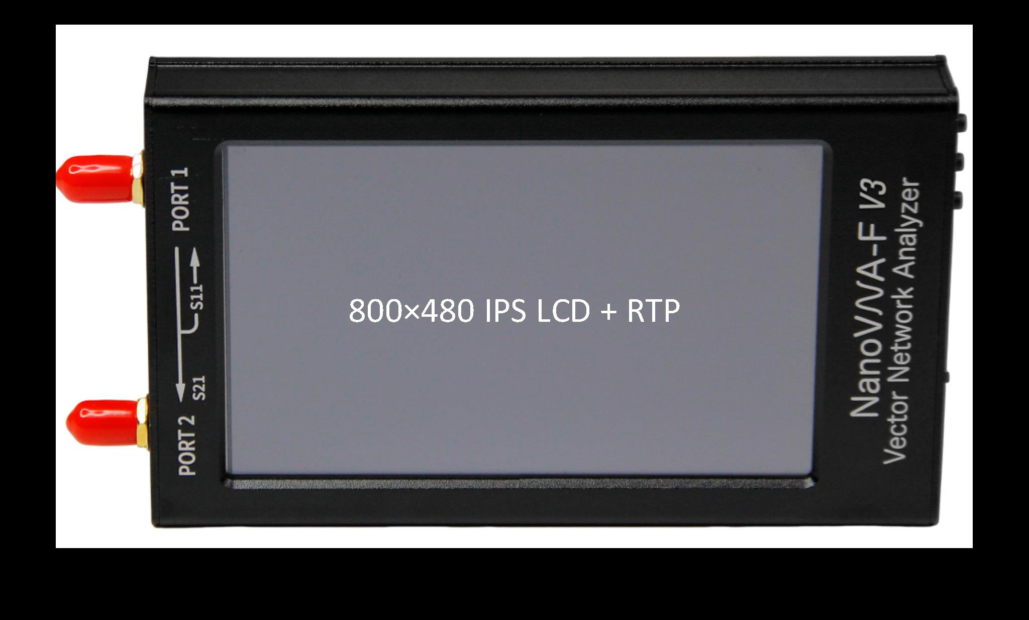
The front panel is dominated by the 4.3-inch IPS display (800 x 480 pixels). The screen uses a resistive touch panel, which means it responds to pressure rather than capacitance — you can operate it with a fingertip, a stylus, or while wearing gloves.
Below the display sit three physical buttons. These provide an alternative to touch navigation and are particularly useful when precision tapping is difficult, such as in cold weather or when wearing gloves.
Physical buttons
Section titled “Physical buttons”| Button | Location | Function |
|---|---|---|
| Left | Leftmost | Power on (long press) / Power off (long press). Also acts as a navigation shortcut. |
| Center | Middle | Push lever: rotary-style navigation. Push to confirm/select. Short press to enter the menu or confirm a selection. |
| Right | Rightmost | Back / Cancel. Returns to the previous menu level or dismisses the current dialog. |
The center button behaves like a push-lever with left/right/up/down directional input, giving you full menu navigation without ever touching the screen. This is the same interaction model used by many bench instruments.
Ports and connectors
Section titled “Ports and connectors”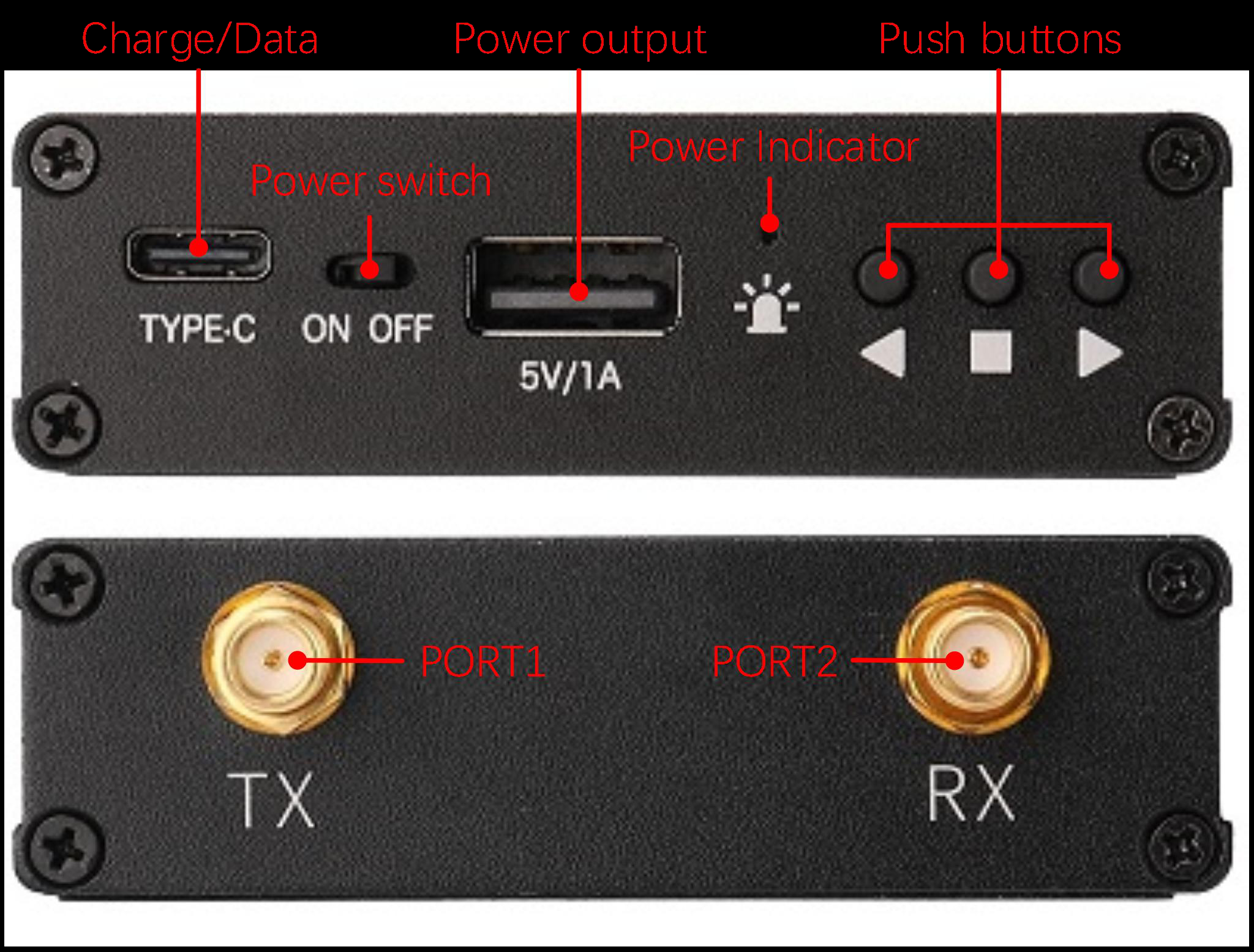
RF ports
Section titled “RF ports”The two SMA female connectors on the top edge of the device carry the RF signals.
| Port | Label | Function |
|---|---|---|
| PORT1 | CH0 | Stimulus output. Also measures reflected signals (S11). Connect your DUT or the calibration standard here for reflection measurements. |
| PORT2 | CH1 | Receives transmitted signals (S21). Connect the output side of a two-port DUT here. |
RF output power is -10 dBm maximum. This is low enough to be safe for most passive components but should not be connected directly to the input of sensitive low-noise amplifiers without appropriate protection.
Data and power ports
Section titled “Data and power ports”| Port | Type | Function |
|---|---|---|
| USB Type-C | Data + Charging | Connects to a PC for remote control, data transfer, and firmware upgrades. Also charges the internal battery (4.7 — 5.5 V input). |
| USB-A | Power output | Provides 5 V / 1 A power output. Useful for powering small accessories, preamps, or a USB light. |
The USB Type-C port supports a virtual COM port for PC software (NanoVNA-Saver, NanoVNA-QT, etc.) and a virtual U-disk interface for firmware upgrades.
Power button
Section titled “Power button”The power button is the leftmost of the three physical buttons on the front panel. Long-press (about 2 seconds) to power on or off. A short press during operation functions as a navigation shortcut.
LED indicators
Section titled “LED indicators”Two LEDs on the device body indicate charging and operating state. The exact behavior depends on whether the device is powered on and whether USB power is connected.
| State | Red LED | Blue LED |
|---|---|---|
| Fully charged (USB connected, device off) | OFF | ON (solid) |
| Working (no USB, device on) | OFF | OFF |
| Low battery (no USB, device on) | OFF | ON (solid) |
| Charging (USB connected, device off) | ON (solid) | FLASH |
| Charging + Working (USB connected, device on) | FLASH | OFF |
Case and build
Section titled “Case and build”The NanoVNA-F V3 uses an aluminum alloy case that serves double duty as structural protection and RF shielding. The metal construction keeps the internals isolated from external interference and provides a solid, confidence-inspiring feel in the hand.
Dimensions: 130 x 75 x 22 mm — roughly the size of a large smartphone, and easy to slip into a tool bag or jacket pocket.
Operating temperature: 0 C to 45 C. Avoid leaving the device in direct sunlight or in a hot vehicle for extended periods — the battery and display are the limiting factors.
Weight: Light enough for one-handed operation but substantial enough to sit stable on a bench.
SMA connectors and cable care
Section titled “SMA connectors and cable care”SMA connectors are precision RF interfaces rated to at least 18 GHz. The NanoVNA-F V3 uses standard SMA female (jack) connectors on both ports.
A few practices will keep your connectors in good condition:
- Align before tightening. Push the connector straight on and start threading by hand. If it resists, back off and realign rather than forcing.
- Finger-tight on the device. Only apply torque to the cable-side nut, never the device-side connector body.
- Keep connectors clean. Dust, skin oils, and corrosion degrade the contact surfaces. A lint-free wipe with isopropyl alcohol works well for routine cleaning.
- Use connector savers for bench setups where you frequently connect and disconnect. A short SMA barrel adapter on each port takes the wear instead of the device connectors.
- Store with caps. When not in use, put the SMA dust caps back on the ports to protect the center pins and mating surfaces.
Included accessories
Section titled “Included accessories”| Item | Quantity | Notes |
|---|---|---|
| SMA calibration kit | 1 set | Open, Short, and 50-ohm Load standards |
| SMA-JJ RG405 cable | 2 | 20 cm semi-rigid, excellent phase stability |
| USB Type-C cable | 1 | Data and charging |
Next: learn the fundamentals of vector network analysis in VNA Basics.