Port Extension
Port extension compensates for the electrical delay introduced by cables, adapters, or fixtures that sit between the calibration reference plane and the actual device under test. It shifts the reference plane forward in the measurement path without requiring a new calibration.
When you need port extension
Section titled “When you need port extension”In an ideal workflow, you calibrate at the exact point where the device under test connects. But sometimes that is not practical:
- Test fixtures: Your DUT mounts in a fixture with built-in transmission lines that cannot be removed for calibration.
- Additional adapters: You need an SMA-to-N adapter (or similar) between the calibrated cable and the DUT.
- Embedded connections: The DUT is soldered to a PCB trace, and you can only calibrate at the board’s SMA connector.
In these cases, port extension tells the NanoVNA to mathematically remove the extra electrical length, so your measurements reflect the DUT alone.
How it works
Section titled “How it works”Every cable or transmission line adds a frequency-dependent phase shift. A signal traveling through 10 cm of coaxial cable arrives later than one that does not traverse that cable. On a Smith chart, this extra delay rotates the impedance plot around the center. On a phase plot, it adds a linear slope.
Port extension applies the inverse of that delay, effectively “unwinding” the rotation and presenting the impedance as if the reference plane were at the DUT.
Measuring open extension
Section titled “Measuring open extension”The simplest way to determine the correct port extension value is to let the NanoVNA measure it for you.
-
Calibrate normally. Perform a full OSLT calibration at the connector you have access to (the existing reference plane). Save the calibration.
-
Leave the far end open. Connect the additional cable, adapter, or fixture to PORT1 but leave the far end open (no DUT, no termination). This gives the instrument a known reflection to work with.
-
Navigate to port extension. Tap the screen to open the menu, then go to CAL > PORT EXTENSION.
-
Tap MEASURE OPEN EXTENSION. The NanoVNA sweeps the open-ended cable and calculates the electrical delay automatically. The measured value (in picoseconds) appears in the port extension field.
-
Enable port extension. Make sure port extension is toggled ON in this same menu. The NanoVNA now applies the correction to all subsequent measurements.
Manual calculation
Section titled “Manual calculation”If you prefer to calculate the delay yourself, the formula is:
Delay (ps) = (Cable length in meters) / (Speed of light x Velocity factor) x 10^12For example, a 15 cm length of RG405 cable (velocity factor 0.7):
Delay = 0.15 / (3.0 x 10^8 x 0.7) x 10^12 = 0.15 / 2.1 x 10^8 x 10^12 = 714 psIn practice, the automatic measurement is more accurate because it accounts for connector discontinuities and the actual cable characteristics rather than nominal values.
Verifying port extension
Section titled “Verifying port extension”After enabling port extension, verify it is working:
-
Leave the far end of the cable or fixture open.
-
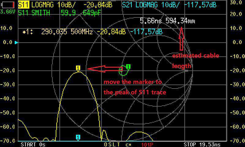
Check the S11 Smith chart. The trace should sit near the far right of the chart (high impedance), without excessive rotation. Before port extension, an open at the end of a cable traces a large arc around the Smith chart as frequency increases. After correct port extension, that arc collapses to a tight cluster near the open-circuit point.
-
Check S11 PHASE. The phase trace should be relatively flat near 0 degrees (for an open) rather than showing a steep linear slope.
If the Smith chart still rotates significantly, the delay value may need adjustment. Increase or decrease it in small increments until the trace tightens up.
Port extension for PORT2
Section titled “Port extension for PORT2”The same concept applies to PORT2 for S21 measurements. If there is extra cable or fixturing between PORT2 and the DUT’s output, you can apply port extension to PORT2 as well. The menu provides separate extension values for each port.
Limitations
Section titled “Limitations”- Frequency-dependent loss is not corrected. Port extension only removes phase delay. If the cable or fixture has loss that changes with frequency, that loss still appears in your measurement.
- Large extensions degrade accuracy. The longer the extension (more delay), the more sensitive the correction is to small errors in the delay value. Keep extensions as short as practical.
- Not a substitute for calibration. Port extension is a supplement to calibration, not a replacement. Always calibrate first, then apply port extension for any remaining path between the cal reference plane and the DUT.
Next steps
Section titled “Next steps”- Full Calibration — the calibration procedure that precedes port extension
- Saving Calibrations — save your setup including port extension settings
- Cable Length with TDR — another way to characterize cable electrical length