Cable Length with TDR
Time Domain Reflectometry (TDR) converts frequency-domain S11 data into a time-domain view, showing reflections along the length of a cable or transmission line. Instead of seeing impedance vs. frequency, you see impedance vs. distance. This makes it straightforward to measure cable length, locate faults, find connector problems, and identify impedance discontinuities.
How TDR works
Section titled “How TDR works”The NanoVNA-F V3 does not send a literal pulse down the cable the way a traditional TDR instrument does. Instead, it sweeps S11 across a range of frequencies and then applies an inverse Fourier transform to convert that frequency data into a time-domain impulse or step response. The result is equivalent — you see reflections plotted against distance.
What you will need
Section titled “What you will need”- NanoVNA-F V3, charged or USB-powered
- SMA calibration kit (OPEN, SHORT, LOAD)
- SMA-JJ RG405 cable (included)
- The cable you want to measure (with appropriate adapter if needed)
- The velocity factor of the cable under test (see table below)
Setting up for TDR
Section titled “Setting up for TDR”-
Set the frequency range.
The sweep range directly affects TDR performance:
- Higher maximum frequency gives better distance resolution (ability to distinguish two closely spaced reflections).
- Lower frequency spacing (more sweep points or narrower span) gives longer maximum measurable distance.
For general cable testing, start with 1 MHz to 900 MHz with 401 or 1001 sweep points. For short cables (under 2 meters), extend to 4.4 GHz for finer resolution.
-
Calibrate.
Perform at minimum a one-port calibration (OPEN, SHORT, LOAD) at the end of the cable connected to PORT1. The reference plane should be at the point where the cable under test will connect.
See Full Calibration for the full procedure.
-
Connect the cable under test.
Attach the cable to PORT1 (or to the calibrated cable end). Leave the far end of the cable under test open (unterminated) for a length measurement, or connect it normally if you are looking for faults along its length.
-
Enable TDR mode.
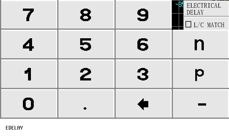
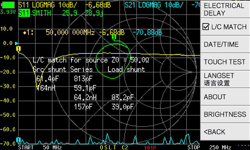
Navigate to DISPLAY > TRACE and select a trace for S11. Then navigate to DISPLAY > FORMAT and scroll down to the TDR options, or navigate through the menu to DISPLAY > TRANSFORM > TRANSFORM ON.
Setting the velocity factor
Section titled “Setting the velocity factor”The velocity factor is critical for converting time delay into physical distance. Every cable type has a characteristic velocity factor — the ratio of signal speed in the cable to the speed of light in vacuum.
-
Navigate to the TDR settings menu.
-
Select VELOCITY FACTOR.
-
Enter the velocity factor as a percentage. For example, for RG405 with a velocity factor of 0.70, enter 70 and press Ok.
Common cable velocity factors
Section titled “Common cable velocity factors”| Cable Type | Velocity Factor | Enter as |
|---|---|---|
| RG405 / Semi-rigid | 0.70 | 70 |
| RG58 | 0.66 | 66 |
| RG213 | 0.66 | 66 |
| RG174 | 0.66 | 66 |
| LMR-400 | 0.85 | 85 |
| LMR-240 | 0.84 | 84 |
| Belden 9913 | 0.84 | 84 |
| RG6 (75 ohm) | 0.82 | 82 |
| RG11 (75 ohm) | 0.78 | 78 |
| Open wire / ladder line | 0.91-0.95 | 91-95 |
| Free space / air | 1.00 | 100 |
TDR processing modes
Section titled “TDR processing modes”The NanoVNA-F V3 offers three processing modes for TDR. Each reveals different information about the cable.
Shows reflections as spikes (impulses) at the distance where they occur. Each impedance discontinuity produces a spike — positive for an increase in impedance (open circuit, connector), negative for a decrease (short circuit).
Best for: Locating discrete faults, finding connectors, identifying damage points. The narrow impulse makes it easy to pinpoint exact locations.
Reading the display: A tall positive spike at the end of the cable means an open termination. A tall negative spike means a short. Smaller spikes along the cable indicate connector joints, kinks, or damage.
Shows the impedance profile along the cable as a step response. The vertical axis represents impedance, and you can read the characteristic impedance at any point along the cable.
Best for: Seeing the impedance of the cable along its length. You can identify sections where the impedance deviates from 50 ohms (or whatever the nominal impedance is).
Reading the display: A flat line at 50 ohms means a uniform 50-ohm cable. A step upward means the impedance increased (e.g., connector, splice, or transition to a different cable type). A step to infinity at the end means open termination.
The default TDR mode. Uses the measurement data as-is without assuming a low-pass response. Suitable when the measurement does not start from a low frequency or when you want a general view.
Best for: Quick surveys, measurements that do not extend down to low frequencies, and situations where the low-pass modes produce artifacts.
Reading the display: Shows reflection magnitude vs. distance. Similar to impulse mode but with broader peaks and less sharp localization.
Window functions
Section titled “Window functions”TDR applies a window function to reduce spectral leakage artifacts (ringing around reflections). Three levels are available:
| Window | Effect |
|---|---|
| MINIMUM | Narrowest peaks (best resolution) but most ringing. Use when you need to separate closely spaced reflections. |
| NORMAL | Balanced tradeoff between resolution and ringing. The default, and a good choice for most measurements. |
| MAXIMUM | Widest peaks (least resolution) but minimal ringing. Use when you want the cleanest display without sidelobes. |
Measuring cable length
Section titled “Measuring cable length”-
Set up TDR mode as described above (calibrate, connect cable, enable TDR, set velocity factor).
-
Leave the far end of the cable open (unterminated).
-
Select LOW PASS IMPULSE mode for the clearest reading.
-
Look for the large positive spike at the far end of the cable. This is the reflection from the open termination.
-
Place a marker on the spike. The marker readout shows the distance from the reference plane to the open end.
Navigate to MARKER > SELECT > MARKER 1, then tap or drag it to the spike, or use SEARCH > MAXIMUM.
-
Read the distance from the marker readout. This is your cable length.
Finding cable faults
Section titled “Finding cable faults”A damaged cable produces reflections at the damage point. Common faults and their TDR signatures:
| Fault | TDR Signature (Impulse Mode) |
|---|---|
| Open circuit (broken center conductor) | Large positive spike |
| Short circuit (shield touching center) | Large negative spike |
| Water ingress | Broad impedance change (gradual bump) |
| Crushed cable | Negative spike (lower impedance at crush point) |
| Loose connector | Small positive/negative spike at connector location |
| Cable splice | Pair of small spikes (impedance bump at each joint) |
-
Connect the cable and enable TDR as described above.
-
Use LOW PASS IMPULSE mode.
-
Look for unexpected spikes between the PORT1 reference point and the cable’s far end.
-
Place a marker on each spike to read its distance from the reference plane.
-
The distance tells you where to look on the physical cable for the problem.
Key relationships for TDR measurements
Section titled “Key relationships for TDR measurements”Understanding these relationships helps you configure the NanoVNA for the best results:
| To improve… | Do this… |
|---|---|
| Distance resolution (separate close reflections) | Increase the maximum sweep frequency |
| Maximum measurable distance | Decrease the frequency spacing (add more sweep points or narrow the span) |
| Measurement accuracy at long distances | Reduce the frequency step size |
| Distance reading accuracy | Use the correct velocity factor and calibrate carefully |
Calibrating velocity factor with a known cable
Section titled “Calibrating velocity factor with a known cable”If you have a cable of known length, you can determine its velocity factor:
-
Connect the known-length cable and enable TDR mode.
-
Set the velocity factor to 100 (speed of light / no correction).
-
Read the distance to the open end.
-
Calculate: Velocity factor = (Actual length / Displayed length) x 100
For example, if the cable is actually 5.0 meters but TDR shows 7.1 meters at VF=100:
VF = (5.0 / 7.1) x 100 = 70.4 -
Enter this value as the velocity factor. The distance reading should now match the known length.
Troubleshooting TDR
Section titled “Troubleshooting TDR”No reflection visible at the cable end
- The cable may be terminated in a matched load (50 ohms). An open or short end produces the strongest reflection. Disconnect the far end.
- The cable may be longer than the maximum measurable distance. Increase sweep points or reduce the stop frequency.
Multiple closely spaced spikes where there should be one
- This is ringing from the window function. Switch to MAXIMUM window to reduce it, or increase the sweep bandwidth for better resolution.
Distance reading does not match the known cable length
- Check the velocity factor. This is the most common source of distance error.
- Verify that the calibration is applied and current.
Next steps
Section titled “Next steps”- Port Extension — related concept for compensating cable delay
- TDR Mode — reference for all TDR settings
- Full Calibration — calibration is essential for accurate TDR